
The Pro Max/ Super Magnum SVS can be installed in
approximately one hour, 30 minutes.
All of the needed hardware is included with the unit.
A quick overview of the installation elements are:
-
Removal of the stock ECU and plenum cover
-
Removal of stock linkage
-
Installation of SVS base unit and slide
-
Installation of SVS progressive linkage
-
Mounting of ECU
-
Linkage adjustment

NOTICE TO PURCHASER:
The SVS system is designed for high-performance use.
The user shall determine the suitability of the product for their
intended application, and user assumes all risks and liability in
connection therein. In no event shall Brucato,
Inc. be responsible for damages or injury from any source.
The following instructions should be read in its
entirety before beginning installation. If you are unsure of performing
any step described, please contact your dealer.
Installation Instructions:
| 1. |
Make sure the ignition
switch is off. Disconnect the battery cables at the battery. |
| 2. |
Disconnect the ECU
wiring harness connector. |
| 3. |
Remove the water sensing
module. |
| 4. |
Remove fasteners holding
ECU in place and lift ECU upward off studs. Disconnect MAP sensor
hose at the manifold and remove the ECU. |
| 5. |
Remove rubber mounts
from top of manifold cover, set aside for later use. |
| 6. |
Note the location of
ground wires for reference during installation. |
| 7. |
Remove the two bolts
on the vapor separator going into manifold cover. Note location
of any spacers for use later. |
| 8. |
Remove any brackets
or screws attached to bottom tabs of manifold cover. Trim relays
may be attached directly to lower cowl pan. FIG
1. |
| 9. |
Remove (12) manifold
cover screws and carefully remove manifold cover so as not to
dislodge the plenum box. |
| 10. |
Inspect rubber gasket
on plenum box, replace if necessary. |
| 11. |
Remove SVS cover assembly
and remove slide. Position SVS base on plenum box and secure
with (12) 1/4-20 x 4 socket head cap screws. Torque screws to
120-inch pounds, working from the center outward. |
| 12. |
Install slide into
recess of base, be sure to correctly insert brass bushing of
slide assembly into elongated slot in linkage. Secure cover
with (4) #10 socket head cap screws and lock washers using loctite,
torque to 25-inch pounds. Check for smooth operation of slide
at this point. |
| 13. |
Refer to FIG
2: Pull throttle actuator arm out of plastic clip A in throttle
advance cam. Remove locking nut B and remove throttle advance
cam. Set aside for later use. |
| 14. |
Refer to FIG
3: Liberally apply grease to throttle pivot shaft C. Install
provided spring D to screw on base linkage E, and screw on throttle
cam linkage assembly F. Stretch linkage assembly onto throttle
pivot shaft C aligning slot over bushing, FIG
4: G. Secure with lock nut removed earlier. Tighten lock
nut to make full contact then back off 1/4 turn. |
| 15. |
Refer to FIG
2: Locate original throttle advance cam previously removed.
Remove plastic swivel A by pushing a 5/16 socket over the back
of the swivel. Push plastic swivel into the new SVS advance
cam, FIG 4: H. Install steel throttle
linkage into plastic swivel H. |
| 16. |
Reattach vapor separator
using existing bolts and spacers. |
| 17. |
Install rubber mounts
to ECU bracket. |
| 18. |
Mount ECU on bracket,
attach ground wire. Connect vacuum line from MAP sensor to manifold.
Connect ECU harness and secure with tie wrap. NOTE: It may be
necessary to space water separating filter out with spacing
washers. |
| 19. |
Reinstall water sensing
module to ECU. |
| 20. |
Refer to FIG
5: The small bracket on the upper port side of the SVS is
a provision for the final fuel filter on older model EFI units.
If so equipped, it may be necessary to route longer fuel lines
between the final fuel filter and the vapor separator. Position
these lines to avoid any kinks. On newer model EFIs with internal
final fuel filter, this bracket is not needed and may be removed. |
| 21. |
Reinstall battery cable. |
Linkage Adjustment:
The following linkage adjustments are to ensure that
the original butterflies operate as originally designed, opening
and closing fully, and that the SVS opens fully, at wide-open throttle
and returns fully closed. These movements should operate smoothly
without binding or having any interference.
| 1. |
Refer to FIG
4: Back off stop screws I and J so as not to interfere with
travel of linkage assembly. Align marks on roller K with mark
on throttle advance cam. Check for .005-.010 inch clearance
between roller and cam. If necessary, adjust by loosening cam
follower screw and moving roller to position, then tighten screw. |
| 2. |
With throttle in idle
position, adjust screw J to achieve .010 inch clearance with
throttle advance cam. Tighten locking nut to prevent movement. |
| 3. |
Have an assistant
operate throttle to wide-open position. IMPORTANT: Original
butterflies MUST be wide open, if necessary, to adjust wide-open
throttle position. Refer to FIG
6: Loosen lock nut and adjust screw L, tighten lock nut.
Operate throttle several times to ensure wide-open throttle.
|
| 4. |
Refer to FIG
4: With throttle in wide-open position, adjust stop screw
I to achieve wide-open throttle of SVS. Operate throttle several
times to ensure wide-open throttle. Tighten locking nut on screw
I to prevent movement. |
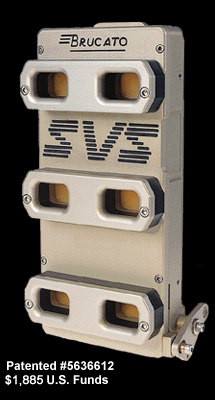
The SVS Stackable Velocity System is a registered
trademark and is patented under #5636612.
The SVS intake system is for use on 1997 or earlier
motors. For use on 1998 or newer models, application must be for
competitive use only. User must determine suitability and proper
use and assumes responsibility for use in all applications, including
compliance with EPA-regulation Emissions Inventory Improvement Program
(EIIP). Brucato, Inc. assumes no liability for
improper application or use of any SVS intake system.
Brucato, Inc.
4743 CHRISTIAN CHAPEL ROAD
NEW HILL, NORTH CAROLINA 27562
(919) 718-0249
FOR PRINTED COPIES OF THESE PAGES, PLEASE SELECT
FROM THE LINKS BELOW:
System
Features | Test Results | Articles
| Instructions & Installation Procedures
| SVS Systems | Home
Page
|